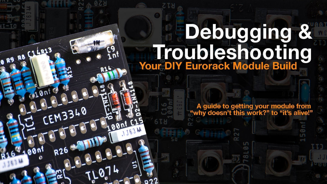
Building your own Eurorack modules is one of the most rewarding parts of modular synthesis — but if you’ve ever spent hours staring at a silent panel or a smoking resistor, you know that troubleshooting is part of the journey. The good news? Debugging is just another form of patching — you’re connecting clues instead of cables.
Here’s a practical approach to help you track down issues, stay sane, and actually learn from the process.
1. Take a Step Back
Before reaching for the multimeter, take a deep breath. Most build issues come down to simple mistakes — missing solder joints, wrong components, or reversed parts.
Grab your BOM (bill of materials) and the schematic if you have it. Don’t assume you know what you did; check it methodically.
Checklist:
• Are all components in the right positions?
• Are all ICs, diodes, and electrolytics oriented correctly?
• Are all solder joints shiny and solid — no bridges or cold joints?
• Are trimmers and jumpers set to their default positions?
It sounds basic, but this step alone solves a huge percentage of non-working builds.
2. Power First — Always
Never plug a new build directly into your case and hope for the best.
Use a bench supply or a fused ribbon cable if possible.
Measure the module’s current draw if possible (or at least check for shorts).
Before powering, measure resistance between +12V, -12V, and GND — if it’s close to zero, you’ve likely got a short.
When you do power up, watch your current draw. If your power supply dips or you smell heat — unplug immediately.
Tip: Touch ICs carefully — if one gets too hot to touch, it’s probably inserted the wrong way or shorted.
3. Check Voltages at Key Points
Use a multimeter to make sure your power rails are actually reaching the ICs and key components.
Start with:
• The power header: ±12V (and sometimes +5V if your design uses it).
• Each op-amp’s power pins (check the datasheet for pin numbers).
• Voltage references or bias points (often 0V, +5V, or mid-rails like +6V).
If one rail is missing, trace it back — often it’s a cracked solder joint or a reversed diode.
4. Signal Tracing — Follow the Path
If voltages are fine but there’s no sound or response, it’s time to follow the signal.
Feed the module a known signal (like a simple oscillator or CV) and probe through the circuit:
• Use an oscilloscope, if you have one.
• Or use your ears — a small powered speaker or “signal sniffer” cable can help.
Start from the input jack and move toward the output stage. When the signal disappears, you’ve found the suspect area.
If the module has multiple stages (e.g. input buffer → OTA → output amp), check each one independently.
5. Think in Sections, Not Components
Instead of staring at a dense PCB, mentally divide the circuit:
• Power
• Input
• Core (filter, oscillator, VCA, etc.)
• Output
Isolate one block at a time. If the output stage works when you inject a signal directly, you know the problem is upstream.
Breaking it down this way saves hours of confusion.
6. Common DIY Gotchas
Some problems come up a lot in DIY Eurorack builds:
Module draws too much current – Power pin short, reversed IC, wrong diode orientation
No sound, LEDs light – Wrong resistor values or swapped op-amp
Distorted output – Power rail missing or op-amp oscillating
Envelope doesn’t trigger – Gate signal not reaching transistor or comparator
LFO/oscillator not running – Timing capacitor or IC pin not soldered
Sometimes a single wrong resistor value can throw the whole circuit off. Double-check your color codes or use a meter.
7. The “One Change at a Time” Rule
When debugging, change only one thing at a time and test again. If you reflow 20 joints and replace 3 ICs, you’ll never know what fixed it.
Keep notes — it sounds nerdy, but it saves you from repeating the same steps.
8. When You’re Stuck
If you’ve been staring at the board for too long:
• Post clear photos on forums like ModWiggler’s DIY section.
• Include power readings, what works/doesn’t, and what you’ve already tried.
• Don’t say “it doesn’t work” — describe how it behaves.
The community is incredibly helpful when you give them solid clues.
9. Celebrate the Fix
When it finally works, document it. Take a photo, share it on your socials, or email your builder community. Every time you debug something, you understand a little more about how synths work — and next time, you’ll fix it faster.
Bonus: Build Debugging Tools
Once you’ve done a few builds, you’ll start to appreciate having some dedicated tools:
• Continuity tester or beeper probe
• Power breakout board with LEDs and fuses
• Test signal generator
• Audio probe cable
• Small oscilloscope (even a USB one helps)
These little helpers make you feel like a proper synth detective.
Final Thoughts
Debugging isn’t failure — it’s feedback. Every time a module doesn’t work, it’s teaching you something about circuits, components, or your own process. The key is to stay patient, stay curious, and keep your iron hot.
Happy building — and may your voltages always be in spec.

